FAQ
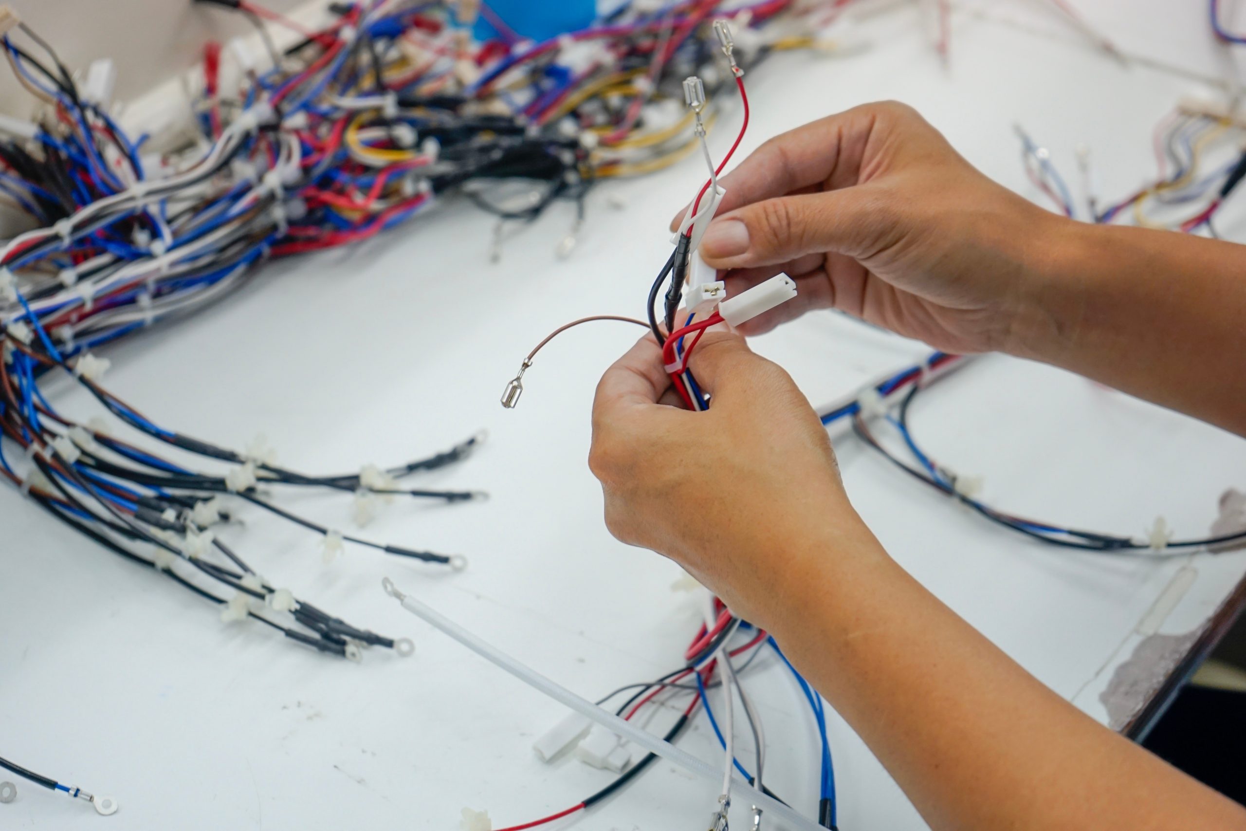
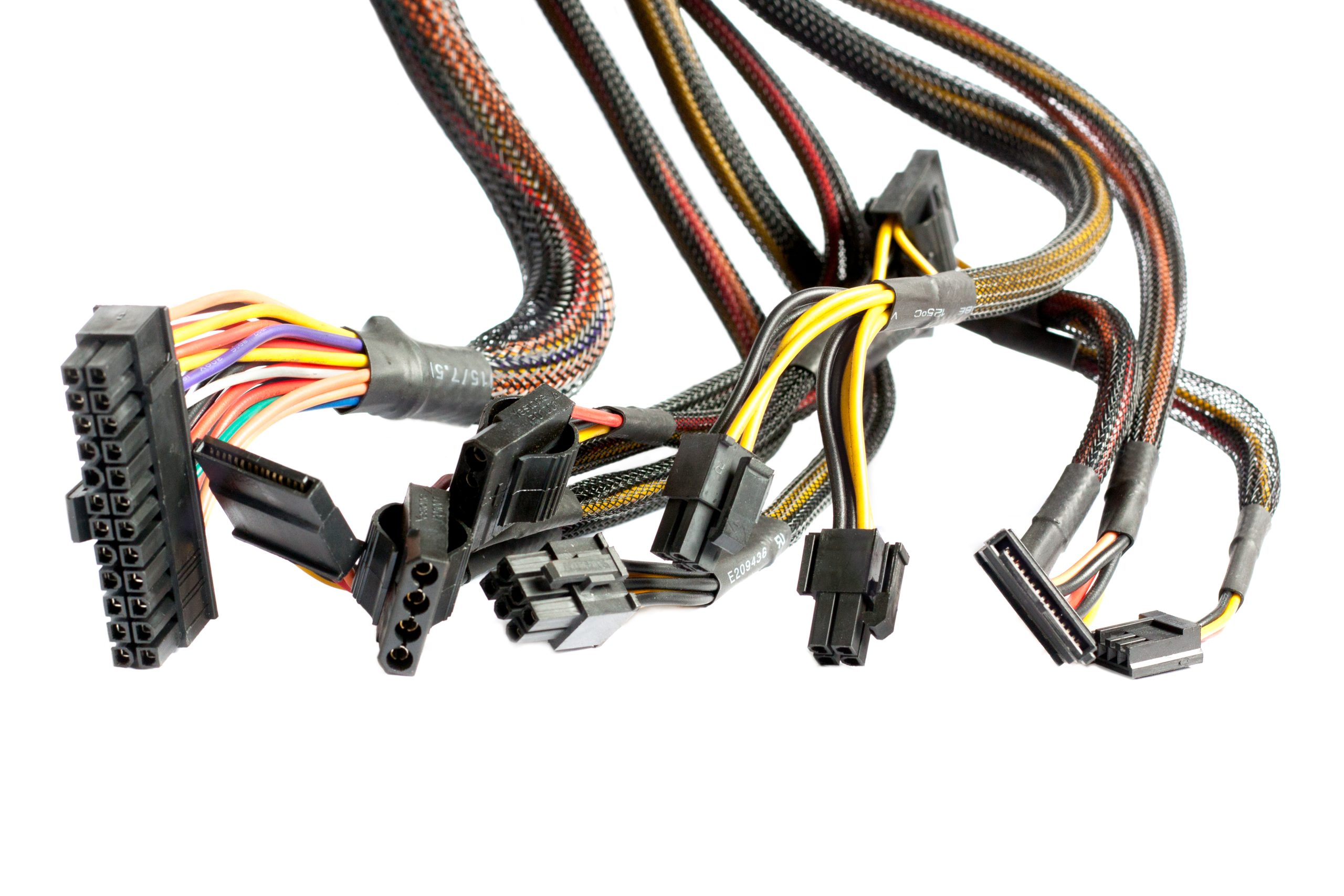
Electrical control cable assemblies are precision-engineered wire harness systems that transmit electronic signals, power, and data between control inputs (sensors, switches, or
electronic control units) and output devices (actuators, displays, or processing systems). They consist of:
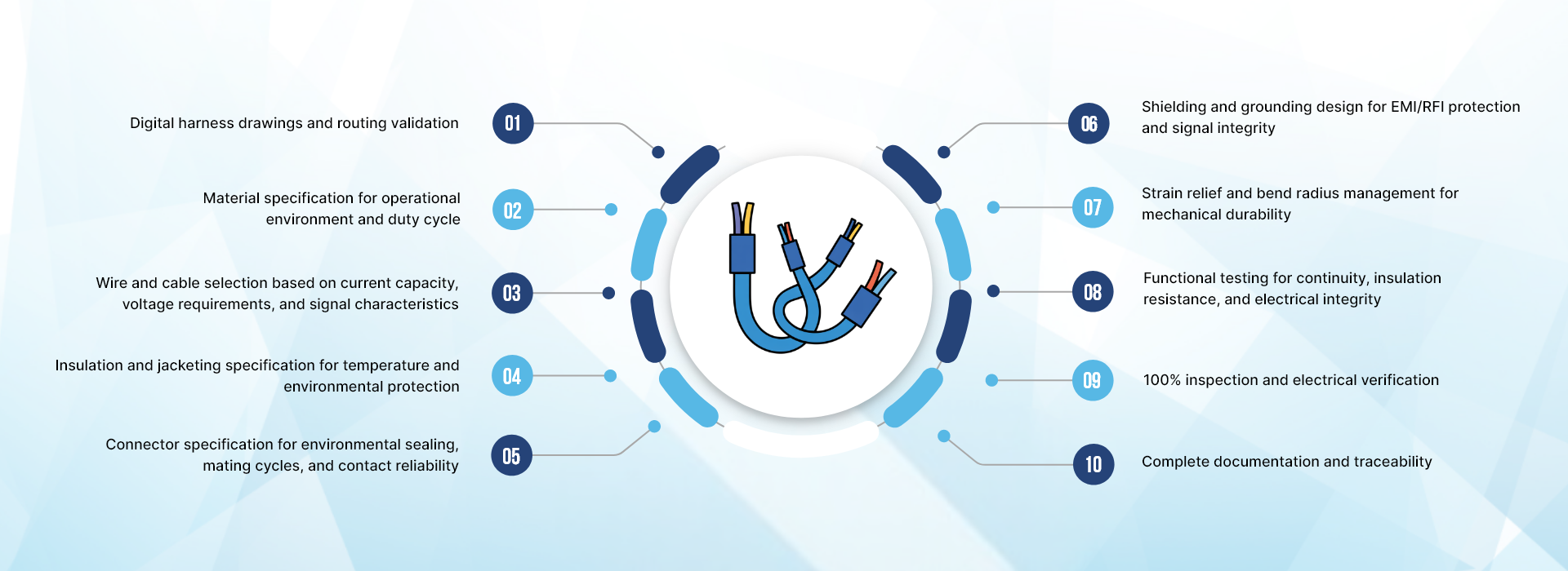
Electrical conductors: Stranded copper wire properly sized for current capacity,
voltage rating, and signal requirements
Insulation and jacketing: Protective materials rated for temperature ranges, abrasion resistance, and chemical exposure
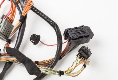
Connectors and terminals: Sealed automotive connectors, industrial circular connectors, terminal blocks, or custom terminations designed for environmental protection and mating cycle requirements
Shielding and grounding: Braided shields, foil shields, or twisted-pair construction for EMI/RFI protection and signal integrity in electrically noisy environments
Protective elements: Heat shrink tubing, conduit, expandable sleeving, and cable armor for mechanical and environmental protection
Strain relief: Properly designed cable exits and support to prevent conductor damage from vibration and flexing Electrical control cable assemblies provide:
Electronic signal transmission with high reliability and accuracy
Integration with electronic control units, sensors, and actuator networks
Precise, programmable control responses and diagnostic capability
Environmental protection for harsh operating conditions
Optimized routing through complex equipment geometry
Reduced installation time and simplified maintenance
Cost-effective electronic control solutions
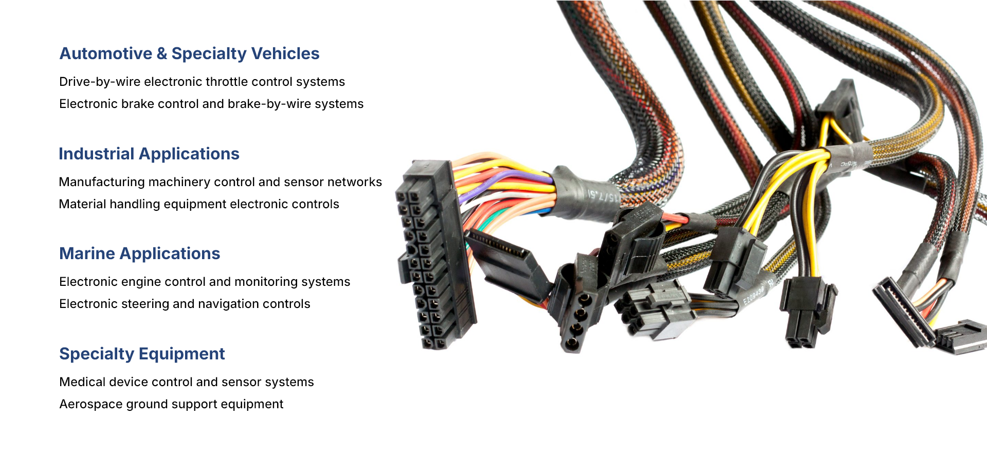
Electrical control cable assemblies are critical components in modern automotive, industrial, and marine systems where electronic controls have replaced traditional mechanical linkages and manual switches.
While both transmit electrical signals and power, automotive and industrial electrical control cable assemblies are engineered for distinctly different operating environments and performance requirements:
Automotive Electrical Control Cable Assemblies:
Designed for dynamic, high-vibration vehicle environments with constant movement
Must withstand extreme temperature ranges (-40°F to 250°F or higher in engine compartments)
Subject to continuous flexing, vibration, and mechanical stress during operation
Require automotive-grade sealed connectors for protection against moisture, road salt, and contaminants
Must meet stringent automotive quality standards (IATF 16949, OEM specifications, environmental testing)
Emphasis on weight reduction, compact packaging, and flexible routing through vehicle chassis
Typical applications: drive-by-wire throttle control, electronic brake systems, transmission controls, sensor feedback, actuator harnesses Industrial Control Panel Cable Assemblies:
Engineered for stationary or semi-stationary industrial equipment installations
Operate in controlled or predictable industrial temperature ranges with defined duty cycles
Experience less dynamic movement but require high reliability over extended service periods (years to decades)
Focus on consistent signal transmission, current capacity, and environmental protection in manufacturing environments
Must maintain performance and calibration over extended operational periods with minimal maintenance
Often installed in control cabinets, equipment enclosures, or along machinery frames
Typical applications: PLC connections, machinery sensor networks, process equipment monitoring, automation control systems
Material and Construction Differences:
Automotive cables often use highly flexible insulation materials (PVC, TPE, cross-linked polyethylene) for routing through tight spaces
Industrial cables may use heavier-duty jacketing for abrasion resistance and protection in manufacturing environments
Connectors are application-specific: automotive uses sealed Deutsch, AMP, or similar connectors; industrial uses circular M12/M8 connectors or terminal blocks
Shielding strategies differ based on EMI/RFI environment and signal sensitivity Wire gauge selection balances current capacity with flexibility requirements
differently for each application
Both require precision manufacturing, rigorous testing, and quality systems, but the specific design parameters, material selection, validation criteria, and testing protocols are optimized
for their respective operating environments and regulatory requirements.
A control panel wire harness represents an integrated solution that combines multiple electrical circuits including control signals, sensor connections, power distribution, and
actuator circuits into a single unified assembly. This integrated approach offers several advantages over individual cable assemblies:
Integrated Functionality:
Combines multiple signal circuits, power distribution, sensor connections, and actuator circuits in one pre-assembled harness
Reduces the number of discrete components requiring individual installation and connection
Simplifies routing, mounting, and strain relief compared to managing separate cable runs
Provides organized, protected pathways for all electrical functions with coordinated branching
Enables common grounding and shielding strategies across multiple circuits
Installation Benefits:
Single harness significantly reduces installation time, labor costs, and potential wiring errors
Pre-assembled, tested, and labeled as a complete system before delivery to customer
Fewer individual connection points reduce potential failure modes and troubleshooting complexity
Simplified documentation with single assembly drawing versus multiple cable specifications
Easier maintenance and replacement procedures with plug-and-play functionality
Reduces on-site installation errors through factory assembly and testing
Design Advantages:
Coordinated circuit routing eliminates physical interference and electrical crosstalk between circuits
Integrated strain relief and environmental protection for entire harness assembly
Consistent labeling, wire color coding, and identification across all circuits
Optimized packaging for space-constrained equipment and control panels
Better control of wire bundling, separation requirements, and bend radius
Simplified cable management with tie points, mounting clips, and support brackets integrated into design Quality and Testing Benefits:
Complete harness tested as integrated system before shipment (continuity, insulation resistance, circuit isolation)
Eliminates field assembly quality variables and installation errors
Ensures proper wire routing, strain relief, and connector orientation
Validates complete system functionality rather than individual circuits
Applications:
Control panel wire harnesses are particularly valuable in:
Industrial control panels requiring multiple PLC I/O connections, sensor inputs, and actuator outputs
Material handling equipment with integrated electronic controls, sensors, and motor connections
Automated machinery combining control signals, power circuits, and feedback sensors
Equipment where installation simplicity, reliability, and reduced field labor are critical
Systems requiring frequent maintenance or replacement where quick disconnect capability is valuable
In Contrast:
Standard electrical control cable assemblies typically consist of single-circuit or simple multi-conductor cables used when:
Individual circuit routing flexibility is required during installation
Circuits are installed at different times or by different contractors
Equipment design requires separate cable entry points
Maintenance strategy calls for individual circuit replacement
Custom field routing is necessary due to site-specific conditions
The choice between integrated wire harnesses and individual cable assemblies depends on equipment design, installation requirements, maintenance strategy, and cost-benefit analysis of factory assembly versus field installation labor.
 We serve clients who require repeatable quality, precise electrical performance, and documented testing for compliance with automotive and industrial standards.