



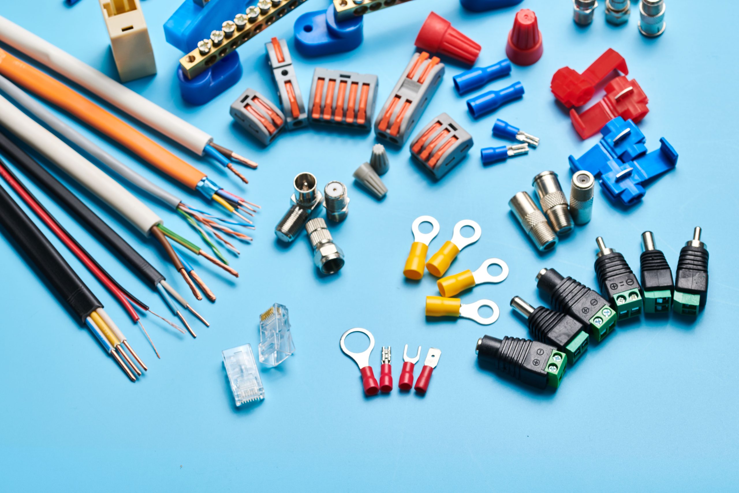
In this post, we’ll cover the key aspects of cable assemblies, including how they differ from wire harnesses, the components commonly used, the manufacturing process, and the situations where a custom cable assembly may be required.
Cable Assembly vs. Wire Harness: What Is the Difference?
A cable assembly is a cable or group of cables terminated with connectors or other interfaces, while a wire harness typically organizes multiple wires or cables into a structured bundle with branches and connection points. The right option depends on the electrical, mechanical, routing, and application requirements.
Before exploring cable assembly types and construction in more detail, it is useful to understand how cable assemblies differ from wire harnesses. Although both provide organized electrical connections, their construction, configuration, and typical applications can vary depending on the system and application. Here are some common distinctions:
| Factor | Cable Assembly | Wire Harness |
| Construction | Typically consists of one or more insulated cables terminated with connectors or other connection components. | Typically groups multiple individual wires or cables into an organized routing structure with branches and connection points. |
| Protection | May use an outer jacket, overmolding, shielding, conduit, or other protective features depending on application requirements. | Often uses sleeving, loom, tape, ties, or conduit to bundle and protect routed conductors. |
| Typical Use | Frequently used for defined power, signal, data, or communication connections between devices or subsystems. | Frequently used to organize and distribute multiple electrical circuits within equipment, machinery, or vehicles. |
| Mechanical Construction | May be built around a jacketed cable with terminations and application-specific protective features. | Typically organizes individual wires and/or cables into a routed bundle using ties, tape, sleeving, loom, or similar methods. |
| Termination | Commonly terminated with connectors, plugs, receptacles, or application-specific interfaces at defined ends. | May incorporate multiple connector and terminal types distributed across branches and breakout points. |
| Installation Approach | Often installed as a defined connection between specific devices, panels, or subsystems. | Often installed along predetermined routing paths to connect multiple locations throughout equipment or a system. |
What Are the Key Cable Assembly Components?
A cable assembly combines multiple components to create a complete electrical interconnection. Each component is selected according to the electrical, mechanical, environmental, and application requirements of the assembly. Common cable assembly components include:
- Conductors and Cables: Conductors provide the electrical path for carrying power, signals, or data. Their material, gauge, strand construction, and insulation are selected according to current capacity, voltage, flexibility, and signal requirements.
- Connectors and Terminals: Connectors and terminals establish electrical and mechanical interfaces between the cable assembly and other components or equipment. Their selection depends on factors such as circuit requirements, connection type, mating configuration, and operating environment.
- Insulation and Jacketing: Insulation electrically isolates individual conductors, while the outer jacket protects the cable from mechanical and environmental exposure. Material selection may depend on temperature, abrasion, chemicals, moisture, and flexibility requirements.
- Shielding: Conductive shielding can be incorporated around individual conductors or cables to help manage electromagnetic interference (EMI) and maintain signal integrity in applications where electrical noise is a concern.
- Strain Relief and Overmolding: Strain-relief helps reduce mechanical stress where cables enter connectors or termination points. Overmolding can provide additional mechanical protection, sealing, and support around these areas when required by the application.
- Sleeving, Conduit, and Protective Components: These additional coverings can be used to protect cables against abrasion, mechanical damage, heat, chemicals, or other application-specific conditions.
- Labels and Identification: Labels, markers, and other identification methods help distinguish cables and connection points while supporting assembly, installation, inspection, servicing, and traceability.
What Are the Common Types of Cable Assemblies?
Cable assemblies are available in different configurations based on their intended function, connection requirements, and operating conditions. Here are some common types of cable assemblies:
- Power Cable Assemblies: Power cable assemblies are complete cable-and-termination configurations designed to transfer electrical power from a source to equipment, components, or distribution points. They typically use conductors, insulation, and connectors or terminals selected for the required voltage and current, with additional protection incorporated where necessary for the operating environment.
- Signal Cable Assemblies: These cable assemblies are designed to carry electrical signals between electronic or electromechanical components such as sensors, controllers, instruments, and actuators. Depending on the signal characteristics and surrounding electrical environment, they may incorporate twisted conductors, shielding, or other construction features to help preserve signal integrity and reduce the effects of electromagnetic interference.
- RF and Coaxial Cable Assemblies: RF Cable Assemblies consist of coaxial cable terminated with compatible RF connectors to transmit radio-frequency and other high-frequency signals between devices or system components. Coaxial cables are designed with a defined characteristic impedance, such as 50 Ω or 75 Ω, and connector/termination quality and transitions need to preserve that impedance.
- Multi-Conductor Cable Assemblies: These assemblies contain multiple individually insulated conductors within a common cable construction and are terminated according to the required system connections. The conductors can be configured to carry power, control, or signal circuits, allowing multiple electrical connections to be incorporated into a single routed assembly.
- Battery Cable Assemblies: Battery cable assemblies are heavy-gauge electrical cable configurations terminated with lugs, terminals, or connectors for carrying high current between a battery and starting, charging, grounding, or power distribution circuits. Their construction is selected to provide the required current-carrying capacity while limiting excessive voltage drop and maintaining secure electrical connections.
- USB Cable Assemblies: USB cable assemblies are connectorized cable configurations designed to provide Universal Serial Bus (USB) connections between compatible devices. Depending on the applicable USB specification and configuration, they can support data transmission, power delivery, or both, with cable construction and connector types selected to meet the required electrical and interface specifications.
Cable Assembly Manufacturing Process
The cable assembly manufacturing process typically involves the following stages:
- Customer Specification Review: The process begins with a review of customer drawings, bills of materials, connector and terminal specifications, cable requirements, dimensions, tolerances, and applicable quality or testing requirements to confirm the assembly can be manufactured as specified.
- Cable Preparation and Cutting: Cable is measured and cut to the specified length using appropriate processing equipment. Length tolerances and preparation requirements are controlled according to the drawing or work instructions.
- Stripping and Conductor Preparation: Outer jackets and conductor insulation are removed to specified dimensions without damaging the underlying conductors. Depending on the termination method, conductors may also require additional preparation before assembly.
- Terminal and Connector Installation: Conductors are terminated using specified methods such as crimping or soldering and installed into the appropriate connector housings. Correct terminal position, orientation, and retention are important for maintaining the intended electrical connection.
- Protection and Strain Relief: Sleeving, heat-shrink tubing, shielding components, strain-relief features, or overmolding may be added where required to provide mechanical or environmental protection
- Identification and Labeling: Labels, markers, part numbers, or other identification features are applied according to project requirements to support installation, traceability, inspection, and servicing.
- Inspection and Testing: Completed assemblies are inspected and tested according to specified requirements. Depending on the application, this may include visual and dimensional inspection, continuity testing, pin-to-pin verification, and other electrical or mechanical tests before release.
When Does a Project Require a Custom Configuration?
Several application requirements may call for a custom configuration rather than a standard option:
- Unique Connector or Termination Requirements: A custom assembly may be needed when equipment requires specific connector types, terminal styles, pin configurations, mating interfaces, or combinations that are not readily available in standard cable assemblies.
- Limited Space or Complex Routing: Equipment with restricted installation space, defined routing paths, or specific connector orientations may require customized cable lengths, breakout locations, minimum bend-radius requirements, or termination configurations to support proper fit and installation.
- Specific Electrical Requirements: Applications with defined voltage, current, signal, shielding, grounding, or, where applicable, impedance requirements may require conductors, cables, and terminations selected specifically for the electrical characteristics of the system.
- Harsh Operating Conditions: Exposure to high or low temperatures, moisture, chemicals, abrasion, vibration, or other demanding conditions may require application-specific insulation, jacketing, sealing, strain relief, or protective components.
- Repeated Flexing or Movement: Applications involving continuous or repetitive motion may require flexible cable construction, appropriate bend-radius control, strain relief, and routing designed around the expected movement and required flex life.
- Specialized EMI or Signal Integrity Requirements: Systems sensitive to electromagnetic interference or signal degradation may require specific shielding, grounding, conductor arrangements, or controlled-impedance cable construction, depending on the electrical interface.
How to Choose the Right Cable Assembly Components
Selecting the right cable assembly components depends on the electrical, mechanical, environmental, and connection requirements of the application.
- Electrical Requirements: Consider voltage, current, signal characteristics, impedance, shielding, and grounding requirements.
- Mechanical Requirements: Evaluate cable length, flexibility, bend radius, routing, connector orientation, and strain relief requirements.
- Environmental Conditions: Consider temperature, moisture, chemicals, abrasion, vibration, and other operating conditions.
- Connector and Termination Requirements: Select connectors, terminals, and termination methods that match the equipment interface and specified assembly requirements.
Cable Assembly Manufacturing with Stantek
Stantek provides the production capabilities needed to manufacture cable assemblies according to customer specifications and application requirements. Our team supports diverse application requirements with a strong focus on quality, consistency, and dependable manufacturing. Contact Stantek today to discuss your cable assembly project and request a quote.